
Design Memorandum
TO: All Design Section Staff
FROM: Bijan Khaleghi
DATE: April 10, 2009
SUBJECT: AASHTO Guide Specifications for LRFD Seismic Bridge Design Amendments
This design memorandum is an amendment to AASHTO Guide Specifications for LRFD Seismic Bridge Design and revisions 1st edition, 2009. WSDOT requires all new bridges and bridge widenings to be designed in accordance with the requirements of the AASHTO Guide Specifications and WSDOT amendments.
The following items summarize WSDOT’s additional requirements and deviations from the AASHTO Guide Specifications for LRFD Seismic Bridge Design:
|
Article
|
Subject
|
WSDOT Requirements
|
|
3.3
|
Earthquake
Resisting Systems (ERS) Requirements for SDCs C and
D
|
WSDOT
Global Seismic Design Strategies:
Type 1:
Ductile Substructure with Essentially Elastic Superstructure. This category is permissible.
Type 2:
Essentially Elastic Substructure with a Ductile Superstructure. This category is not permissible.
Type 3:
Elastic Superstructure and Substructure with a Fusing Mechanism Between The
Two. This category is permissible with Bridge Design Engineer’s approval.
Foundations
in all SDCs could be designed for the minimum of
the linear elastic forces or the capacity protection forces. If foundations are designed for elastic
forces, no inelastic deformation is anticipated, but minimum detailing is
required according to the bridge seismic design category. Shear design shall be based on 1.2 times
elastic shear force and nominal material strengths shall be used.
|
|
3.3
|
Earthquake
Resisting Systems (ERS) Requirements for SDCs C and
D
|
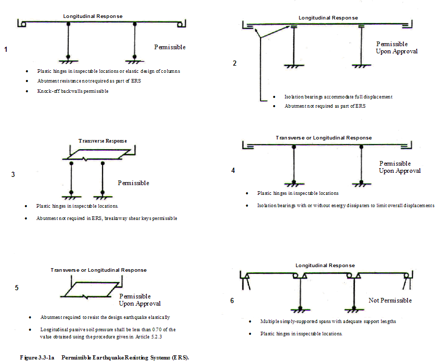
Figure
3.3-1a: Permissible Earthquake Resisting System (ERS), see attachment.
- Types 1 and 3 are permissible.
- Types 2, 4 & 5 are permissible with Bridge Design Engineer’s
approval.
- Type 6 is not Permissible.
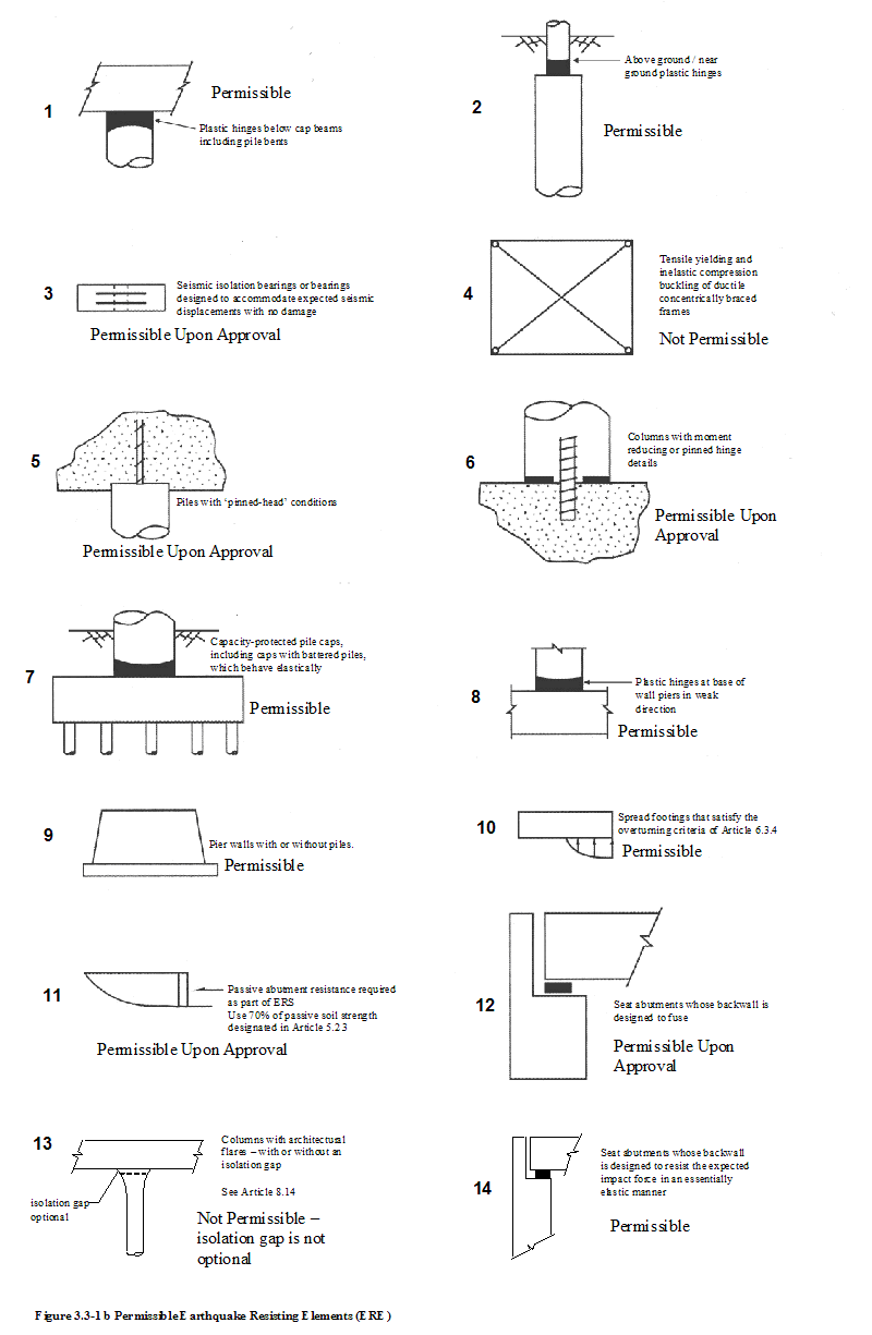
Figure
3.3-1b: Permissible Earthquake Resisting Elements (ERE), see attachment.
- Types 1, 2, 7, 8, 9, 10 &14 are permissible ERE.
- Types 3, 5, 6, 11, 12 are permissible ERE with Bridge Design
Engineer’s approval.
- Types 4 &13 are not permissible.
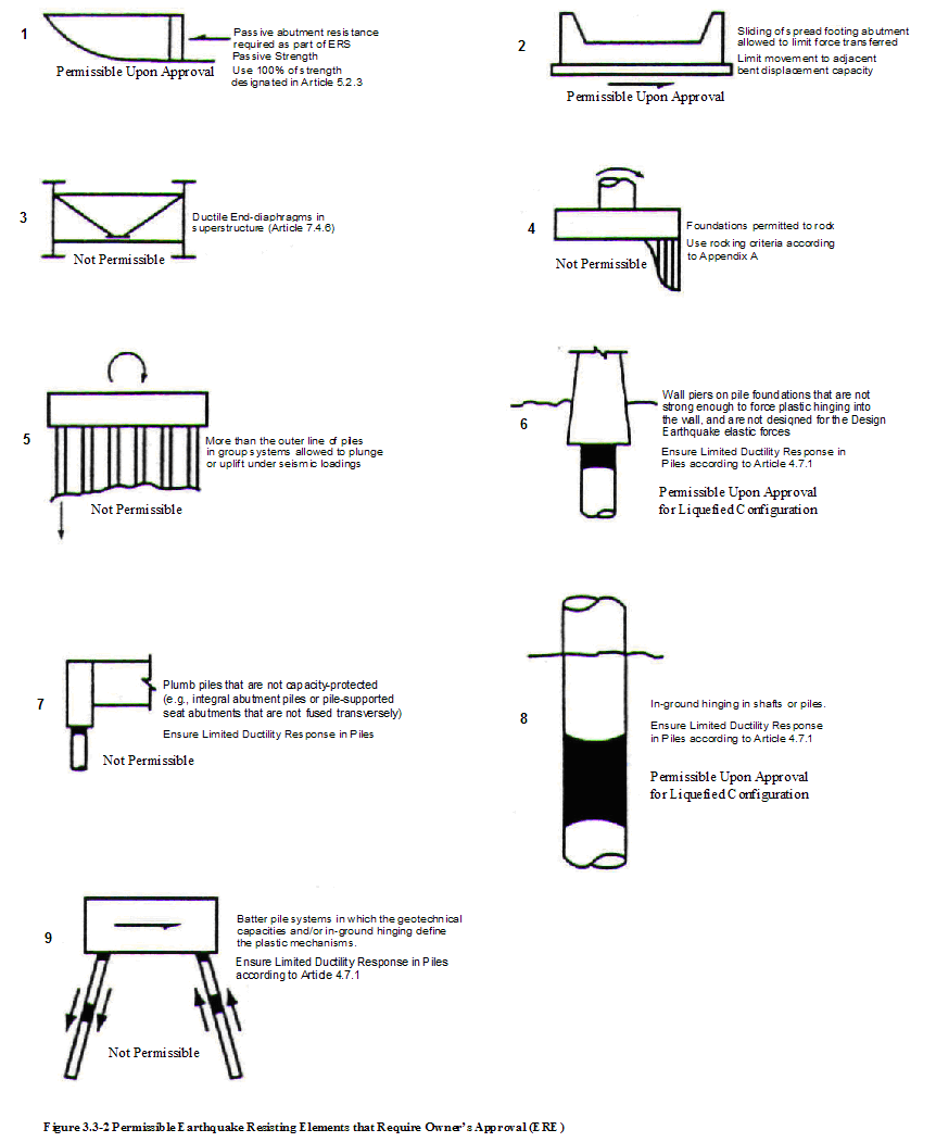
Figure
3.3-2: Permissible Earthquake Resisting Elements that require Owner’s
Approval (ERE), see attachment.
- Types 1 & 2 are permissible ERE with Bridge Design
Engineer’s approval.
- Types 6 & 8 are not Permissible for Non-liquefied
configuration and Permissible with Bridge Design Engineer’s approval for
liquefied configuration
- Types 3, 4, 5, 7 & 9 are not Permissible.
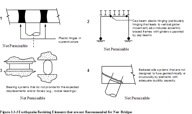
Figure
3.3-3: Earthquake Resisting Elements that are not Recommended for New Bridges
- Types 1, 2, 3, & 4 are not Permissible.
Permissible
ERS and ERE systems with Bridge Design Engineer’s approval are applicable to
all projects regardless of contracting methods.
|
|
3.4
|
Seismic
Ground Shaking Hazard
|
The
procedure used to determine the ground shaking hazard for site class F,
critical or essential bridges shall be based on the WSDOT Geotechnical
Engineer recommendations.
|
|
3.5
|
Selection
of Seismic Design Category (SDCs)
|
Pushover
Analysis shall be used to determine displacement capacity for both SDCs C and D.
|
|
3.6
|
Temporary
and Staged Construction
|
Design
response spectra for temporary and staged construction bridges may be reduced
by a factor of not more than 2.5.
However, it shall be clear in the contract document that structure is
designed for reduced response spectra.
|
|
3.7
|
Load and
Resistance Factors
|
Use load
factor of 0.0 for live load.
|
|
4.1.2
4.1.3
|
Balanced
Stiffness SDCs
D
Balanced
Frame Geometry SDCs D
|
Balanced
stiffness requirements and balanced frame geometry requirement shall be
satisfied for bridges in both SDCs C and D. Deviation from balanced stiffness and
balanced frame geometry requirements shall be approved by Bridge Design
Engineer.
|
|
4.2
|
Selection
of Analysis Procedure to Determine Seismic Demand
|
Analysis
Procedures:
Procedure 1
(Equivalent Static Analysis) shall not be used.
Procedure 2
(Elastic Dynamic Analysis) shall be used for all regular bridges with 2
through 6 spans.
Procedure 3
(Nonlinear Time History) may be used where applicable. The time histories of
input acceleration used to describe the earthquake loads shall be selected in
consultation with WSDOT Geotechnical Engineer and Bridge Design Engineer.
|
|
4.9
|
Member
Ductility Requirement for SDCs D
|
In-ground
hinging for drilled shaft and pile foundations may be considered for
liquefied configuration with WSDOT Bridge Design Engineer approval.
|
|
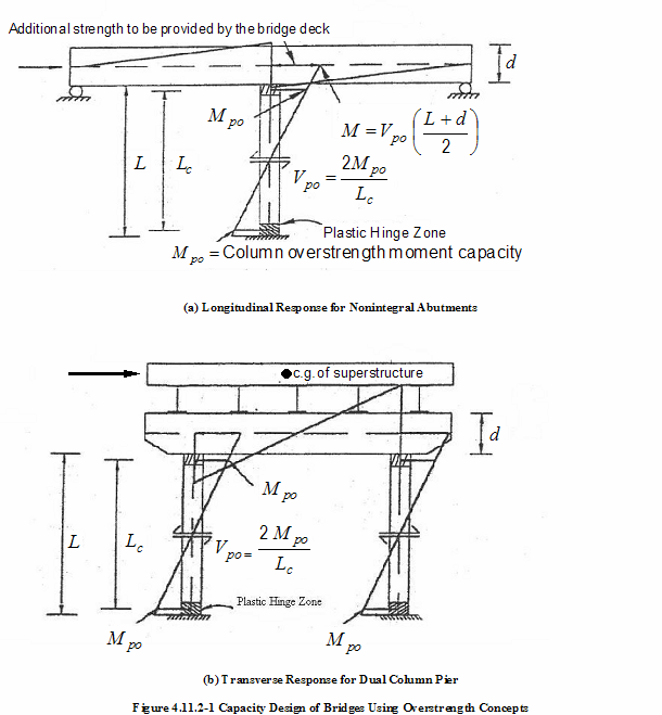
4.11.2
|
Plastic
Hinging Forces
|
Revise
Figure 4.11.2-1, see attachment.
|
|
4.12.3
|
Minimum
Support Length Requirements Seismic Design Category D
|
For
single-span bridges, the support length shall be 150% of the empirical
support length, N, specified by Equation 4.12.2-1
|
|
4.13.1
|
Longitudinal
Restrainers
|
Longitudinal
restrainers shall be provided at the expansions between superstructure
segments. Restrainers shall be designed for a force calculated as the acceleration
coefficient, As, as specified in Eq.3.4.1-1, times the permanent load of the
lighter of the two adjoining spans or parts of the structure. Restrainers
shall be detailed in accordance with the requirements of WSDOT BDM Section
4.3.5. Restrainers may be omitted for SDCs C and D where the available seat width exceeds the
calculated support length specified in Eq. 1 (using 2 times seismic
displacement instead of 1.65 as required in Eq. 4.12.3-1).
N=(4+2.0Δeq)(1+0.00025S2)
≥ 24 in. (1)
Omitting
restrainers for liquefiable sites shall be based on the WSDOT Bridge Design
Engineer’s approval.
Longitudinal
restrainers shall not be used at the end piers (abutments).
|
|
5.2
|
Abutments
|
Diaphragm
Abutment type shown in Figure 5.2.3.2-1 shall not be used for WSDOT bridges.
With WSDOT
Bridge Design Engineer approval, the abutment may be considered and designed
as part of earthquake resisting system (ERS) in the longitudinal direction of
a straight bridge with little or no skew and with a continuous deck. Longitudinal passive soil pressure shall be
less than 50% of the value obtained using the procedure given in Article
5.2.3.3.
Participation
of wingwall in transverse direction may not be
considered in the seismic design of bridges.
|
|
5.3
|
Foundation
- general
|
The
required foundation modeling method (FMM) and the requirements for estimation
of foundation springs for spread footings, pile foundations, and drilled
shafts shall be based on the WSDOT Geotechnical Engineer’s recommendations.
|
|
5.6.2
|
Figure 5.6.2-1
|
The
horizontal axis label of Figure 5.6.2-1 for both (a) Circular Sections and
(b) Rectangular sections shall be
Axial Load
Ratio 
|
|
5.6.3
|
Ieff for Box Girder Superstructure
|
Gross
moment of inertia shall be used for box girder superstructure modeling.
|
|
6.3.9
|
Foundation
Rocking
|
Foundation
rocking shall not be used for the design of WSDOT bridges.
|
|
C6.5
|
Drilled
Shafts
|
The scale
factor for P-y curves for large diameter shafts shall not be used for WSDOT
bridges. Unless approved by WSDOT Geotechnical Engineer and Bridge Design
Engineer.
|
|
6.7.1
|
Longitudinal
Direction Requirements
|
Case 2:
Earthquake Resisting System (ERS) with abutment contribution may be used
provided that the mobilized longitudinal passive pressure is less than the
0.50 of the value obtained using procedure given in Article 5.2. 3.3.
|
|
6.8
|
Liquefaction
Design Requirements
|
Soil liquefaction assessment
shall be based on the WSDOT Geotechnical Engineer’s recommendation and GDM
Section 6.4.2.8.
|
|
8.4.1
|
Reinforcing
Steel
|
Only ASTM A
706 reinforcing steel shall be used.
Deformed
welded wire fabric may be used with Bridge Design Engineer’s approval.
Wire rope
or strands for spirals, and high strength bars with yield strength in excess
of 75 ksi shall not be used for design purposes.
|
|
8.5
|
Plastic
Moment Capacity for Ductile Concrete Members for SDCs
B, C and D
|
The overstrength magnifier of 1.2 for ASTM A 706
reinforcement shall be applied to column plastic hinging moment to determine
force demand for capacity protected members connected to a hinging member.
|
|
8.6.1
|
Shear Demand and Capacity
|
The shear
reinforcement outside plastic hinge region need not exceed the required shear
reinforcement inside the plastic hinge region.
|
|
8.6.7
|
Interlocking
Bar Size
|
Same bar
sizes may be used inside and outside of interlocking spirals.
|
|
8.8.2
|
Minimum
Longitudinal Reinforcement
|
Minimum
longitudinal reinforcement of 1% shall be used for columns in SDCs B, C, and D.
|
|
8.8.10
|
Development
length for Column Bars Extended into Oversized Pile Shafts for SDCs C and D
|
Extending
column bars into oversized shaft shall be based on either a staggered manner
as described in Article 8.8.2, or per current BDM practice based on TRAC
Report WA-RD 417.1 "Non Contact Lap Splice in Bridge Column-Shaft
Connections” and Design Memo “Column-Shaft connection Design and Detailing
Recommendation” dated as July 18, 2008.
Same size
column-shaft is not permissible unless approved by Bridge Design Engineer.
|
|
8.8.12
|
Lateral
Confinement for Oversized Pile Shaft for SDCs C and
D
|
The requirement
of this article for shaft lateral reinforcement may be replaced with the
recommendations of July 18, 2008 Design Memorandum.
|
|
8.9
|
Requirements
for Capacity Protected members
|
Add paragraphs as follows:
For SDCs C and D where liquefaction is
identified, with Bridge Design Engineer’s approval, pile and drilled shaft
in-ground plastic hinging may be considered as an ERE. The bridges should be
analyzed and designed in both nonliquefied
configuration and liquefied configuration in accordance with Article 6.8.
In nonliquefied configuration, the
capacity protected members shall be designed in accordance with the
requirements of Article 4.11. The pile
and drilled shaft shall be designed for a flexural expected nominal capacity
equal to 1.25 times the moment demand generated by the overstrength
column plastic hinge moment. Plastic
hinges shall only be permitted at locations in columns where they can be
readily inspected and/or repaired.
In liquefied
configuration, the capacity protected members shall be designed in accordance
with the requirements of Article 4.11 except the pile and drilled shaft shall
be designed for a flexural expected nominal capacity equal to 1.0 times the
moment demand generated by the overstrength column
plastic hinge moment.
|
|
8.10
|
Superstructure
Capacity design for Integral Bent Caps for Longitudinal direction for SDCs B, C and D
|
The
effective width for open soffit girder-deck superstructure as specified in
Article 8.10 shall be used instead of current WSDOT practice based on the tributary
number of girders per column. The
requirement of Article 8.11 for eccentricity between the plastic hinge
location and CG of bent cap applies.
|
|
8.12
|
Superstructure
Design for Non-Integral Bent Caps for SDCs C &
D
|
Non-Integral
Bent Caps shall not be used for continuous concrete bridges in SDCs B, C and D.
|
|
C 8.13
|
Joint
Design for SDCs C and D
|
Add
commentary as follows:
Additional
joint reinforcement specified in Article 8.13.4.2 for integral bent cap and
Article 8.13.5.1 for nonintegral bent cap is based
on the tests by Priestley (1996) and Sritharan
(2005) for certain standard joint as shown in Figure C8.13.1-1 and Figure
8.13.4.2-1-2 using the external strut force transfer method. The column longitudinal bars for these
joint shall be extended into the cap beam as close as practically possible to
the deck for integral bent cap and top of cap beam for nonintegral
bent cap. The joint reinforcement
shall be placed within a distance of 0.5 Dc from the column surface. Consequently, these specifications only
applicable to the joints that closely match the geometry of test joints and
can be detailed as shown in Figure 8.13.4.2-1-1 to 3 and Figure 8.13.5.1.1-1
to 2. Bent cap beams not satisfying
these joint geometry and detail requirements shall be designed based upon the
strut and tie provisions of the AASHTO LRFD Bridge Design Specifications.
|
|
8.15
|
Column
Shear Key Design for SDCs C and D
|
Add
paragraphs as follows:
The column
hinge shall be designed in accordance with Article 5.8.4 provisions for shear
friction of the AASHTO LRFD Bridge Design Specifications using the nominal
material strength properties. The design procedure and hinge detail per TRAC
Report WA-RD 220.1 titled “Moment-Reducing Hinge Details for the Based of
Bridge Columns” should be used. The
thickness of the expansion joint filler shall allow the maximum column
rotation without crushing the edge of the column concrete against the cap
beam or footing.
|
Background:
This design memorandum describes WSDOT’s amendments to AASHTO Guide Specifications for LRFD Seismic Bridge Design 1st edition, 2009 based on the WSDOT design and construction requirements. This memorandum supersedes design memorandum issued on November 14, 2008.
If you have any questions regarding these issues, please contact Bijan Khaleghi at 705-7181 or Chyuan-Shen Lee at 705-7441.
cc: Mohammad Sheikhizadeh, Bridge Construction - 47354
F. Posner, Bridge and Structures – 47340
Note: For a PDF of this design memo, click here.
The following items are some clarifications and revisions which were added on May 14, 2009:
3.3 Earthquake Resisting Systems (ERS) Requirements for SDCs C and D:
Foundations in all SDCs could be designed for the minimum of the linear elastic forces or the capacity protection forces.
If foundations are designed for elastic forces, no inelastic deformation is anticipated, but minimum detailing is required
according to the bridge seismic design category. Shear design shall be based on 1.2 times elastic shear force and nominal
material strengths shall be used.
4.9 Member Ductility Requirement for SDC D:
In-ground hinging for drilled shaft and pile foundations may be considered for liquefied configuration with WSDOT Bridge
Design Engineer approval.
8.8.2 Minimum Longitudinal Reinforcement:
Minimum longitudinal reinf. of 1% shall be used for columns in SDCs C and D.
8.8.12 Lateral Confinement for Oversized Pile Shaft for SDCs C and D:
The requirement of this article for shaft lateral reinforcement may be replaced with the recommendations of July 18, 2008
Design Memorandum.
8.9 Requirements for Capacity Protected members:
In liquefied and nonliquefied soil configurations, the capacity protected members shall be designed in accordance with the
requirements of Article 4.11. The drilled shaft shall be designed for a flexural expected nominal capacity equal to 1.0 times
the moment demand generated by the overstrength column plastic hinge moment provided that the lateral confinement for
oversized shafts for SDCs C and D are based on moment-curvature analysis and ductility.
|